
There is a very good article “Comparison of ESP8266 NodeMCU development boards” written by Marcel Stör that helps to understand the differences between the actual NodeMCU variants.
Yesterday I got some LoLin devices ordered from banggood.com and had to recognize that the form factor of this boards is similar to the original NodeMCU-devkit v0.9 (v1).
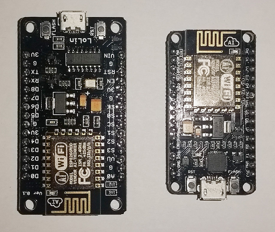
The following images compare the LoLin NodeMCU (v3) with an Amica NodeMCU (v2).

NodeMCU is open source hardware and software. Therefore this is no problem in general. But, if you want to include a NodeMCU-devkit into an existing baseboard you can run into problems if you do not consider such possible differences.
The Grove Base Board for NodeMCU is equipped with (female) headers that allow plugging both NodeMCU variants. Not all baseboards offer this degree of freedom.

[…] out though for the difference in size! This LoLin board is significantly larger than the Amica and DOIT V2 […]
LikeLike
Thanks for showing the difference in size. You helped save me from the frustration of getting a LoLin variant.
LikeLiked by 1 person
There’s a new board available that seems very promising, the D1-mini, currently sells for $4 on AliExpress, has a very compact double-sided design, on-board CH340G, low-dropout LDO regulator (RT-9013), and breaks out only 16 useful pins to keep compact.
LikeLike
I ordered D1 mini and DHT11 shield today to build a “matchbox weather station”.
LikeLike
Forgot to add URL: http://www.wemos.cc/wiki/doku.php?id=en:d1_mini
There’s also a DHT11 shield for $2.50
They also have a larger Arduino-sized board that’s form-factor compatible with Arduino shields
Greg.
LikeLike
Well now the fun never stops, there’s also one called the ‘Witty’ which looks like exactly what I’ve been looking for, i.e. an ESP board with the ‘NorthBridge’ (USB/power) part on a separate board, that you can remove for deployment once F/W is flashed. And it is dirt cheap (< $3), look-up Witty ESP8266 on Ali….
I have not found the specs yet. There are links to Baidu, all in chinese… It looks like there are two micro USB sockets, one on the USB/TTL northbridge daughter board, one on the ESP holder main board, so presumably the VReg is on the upper board too, I have no idea which model that is.
This looks really slick!
Greg.
LikeLike
It’s in my order at Aliexpress already 😉
LikeLike
The Witty boards do not follow best practices for board layout design. Most obvious being the components mounted on the opposite side of the antenna trace, which should be left clear to avoid wifi signal interference. Who knows what other odd decisions they made in their design? I’m sticking with Amica v2s or Wemos D1 Minis for my projects (which I’ll admit isn’t much).
LikeLiked by 1 person
The most time I work with Amica and D1 mini. So I have not much experience with Witty.
The D1 mini combined with the available shield for it is a very good solution for small IoT nodes.
See the updated DHT11 application, for example. It works very stable now.
LikeLike
Good point Mark. I would like to do some range test of the various ESPs (I can do bare -01, -03, -07 (w|w/o ant), -12, -12E, -14, NodeMCU v2,v3, Witty…), Even the way you mount a ‘bare’ ESP-xx on breadboard (with metallic rails below) will probably affect signal range, would be an interesting study to conduct.
LikeLike
Now, the Witty is still as low as $2.52 on ali, vs still and steady $4 for D1 Mini, and $3.29 for NodeMCu v3.
I wish there were a true Ultimate board, with the Witty form factor and modularity, but with ESP’s antenna sticking out and 3.3V break out, and a low-power buck converter that could run off a 3.7V LiPo or 5V USB…
LikeLike
Looks like the latest Nodemcu firmware has pin mappings for the amica board so d1 is 1 and d2 is 2 etc. Had quite a time finding which pin is which.
LikeLike
[…] Node MCU Setup NodeMCU Variants nodeMCU with Lua and its native tools Comparison of ESP8266 NodeMCU development […]
LikeLike
I’ve just become interested in the ESP8266 WiFi SoC in over the last 4 or 5 weeks, and I have two WeMOS D1 boad and two LoLin NodeMCU board. My query today has to do eithe the LoLin NodeMCU v3 board, and NodeMCU board in general. If you look at the NodeMCU board positioned so that the WiFi antenna is up and the Micro-USB connector is down, then you can read the silk-screened pin names. For an Arduino user, the pins on the right side are mostly self-explanatory. But, on the left side there are six pins which I call the “mysterious pins”. These are the ones labeled on NodeMCU V2 and V3 as S3, S2, S1, SC, S0, and SK. The pinout diagram available for the LoLin NodeMCU shows that these 6 pins have the following functions: GPIO10, GPIO9, MOSI, CS, MISO and SCK, and also they have another set of functions called SDD3, SDD2, SDD1, SDCMD, SDD0, and SDCLK. Collectively these 6 “SD” pins are classified as being “SDIO” and the MOSI, CS, MISO and SCK pins are classified as SPI. However, ther are other seemingly SPI related pins on the right side of the NodeMCU identified as HSCK, HMISO, HMOSI, and HCS, Does this mean there are two SPI ports on the LoLin NodeMCU? or are these pins just duplicates of each other. I have used SPI before with Arduino Unos, but I have yet to be successful implementing SPI on the LoLin NodeMCU board. Anyone have a tutorial that demonstrates how to use SPI with NodeMCUs? Also, what’s the story behind all these mysterious pin names? On R1, most of these mysterious pins were either marked “RSV” (and NC) or was a 3.3V or GND pin. How does one typically use the SDIO pins? And what’s the deal with GPIO10 and GPIO9. I thought they were used internally by the ESP8266 SoC along with GPIO6, GPIO7, GPIO8, and GPIO11. Did Espressif redesign their ESP-12E module in such a way as to free up a couple GPIO pins for general use, or are these special pins made available just to extend some capability of the ESP8266F? The documentation is pretty poor for this product, and depending on ESP8266 documentation from other vendors not exactly the same products just creates more questions than they answer. So hopefully some of you more experienced users can help clue me it. I relate to this device as a Arduino on steroids (except maybe the 3.3V stumbling part). I have gotten the WeMos D1 up running the Advanced Server and I modified the little website to provide essentially a ESP8266 links page, seems a lot easier to use and much more reliable than a WizNet 5100 Ethernet Shield (based on my sample size of 1 testing)..
LikeLike
There are indeed two separate SPI busses on the ESP8266 board. One is intended for system use only so that the ESP8266 SoC can address its on-board memory. On the pin-out diagrams for NodeMCU pins they like to classify this as the SPI interface (misleading folks to attempt to use that SPI bus for their application because the alternative bus “HSPI” sounds too strange). In fact the HSPI bus is the actual SPI bus intended for application developers to use. The “H” in “HSPI” stands for “Hardware” and the ESP8266 chip includes on-dye circuitry to perform SPI without doing software SPI, and the result is a much higher speed SPI interface as compared to doing it in software (by a factor of maybe 8 to 10). The thing to remember is that GPIO pins 6, 7, 8, 9, 10 and 11 are reserved for system use only (flash memory addressing), so hands off. Using these pins will likely crash your ESP8266. On most ESP8266 boards, the system flash memory uses what known as “Quad-IO” (“QIO”) SPI where ther are four GPIO address lines being used. However, there are some versions of the NodeMCU board which have had some modification done to implement “Dual-I/O” (“DIO”) SPI, freeing up two GPIO lines which are so far rumored to be available for general usage. Part of the problem that people face in attempting to use them is that the development environment also has to support it (Dual-IO SPI), and if you haven’t enabled it (or your development environment just doesn’t support it), then the fabled GPIO9 and GPIO10 pins are just not usable. Have heard eLua supports it, but maybe not the Arduino IDE/C w/ESP8266 core installed, and I still noit sure about MicroPython, though they have a softeware install option with the esptool.py utility which is supposed to enable DUAL-IO SPI. That esptool.py command option is “-fm dio”. Whether this also makes GPIO9 and GPIO10 available remains to be seen.
LikeLiked by 1 person
Oh, the other thing about the LoLin NodeMCU… it is 3cm wide, which is the same width as the center 10 pins of those white solder-less breadboards, so once you plug the LoLin MCU board into the breadboard, there are no pin holes accessible with which you can jumper signals to and from the device with, What I had to do is take two of the white solder-less breadboards and on one I removed the lower power rails, and the on the other I removed the top power rails. I plugged in the LoLin NodeMCU such that there was 1.5cm gap between the two breadboards and 3 available pin holes for each NodeMCU pin. With the NodeMCU acting as a spacer, I stripped off the backing paper on the double sided tape and stuck the whole thing down on a wooden board to give the assembly some stability. Since then I also discovered these tiny 4.7 x 3.5 cm breadboard which I originally got with a couple of Arduino prototype shields. These can also be bought separately for a lot cheaper than a full size or even a half size breadboard. (I’d call thes a quarter-sized and w/o power rails). I’m sure some of you guys may have better ways to breadboard these “fat” LoLin NodeMCUs, but my method works well enough for me, Maybe next time I’ll buy and try an Amica NodeMCU R2.
LikeLike
After my first order of Lolin I had no good surprise. For bread board applications I use only Amica or D1 mini. Lolin can be used with the Lolin base board w/o these problems.
LikeLike
Buying a “base board” for the LoLin is like doubling the price of the board. I prefer just buying two of those mini breadboards and using the LoLin board as a spacer, plug it into the two mini breadboards with maybe a 1 cm (or 1.5 cm?) gap between the two mini breadboards. Then peel off the backing paper off the back of the two mini breadboards and “plop” the whole assembly down onto a suitably sized plywood or Plexiglas board.
LikeLike
OK, so I bought two “Geekcreit™ Doit NodeMcu Lua ESP8266 ESP-12E” devboards from Banggood.com (http://tinyurl.com/ztvpsbf) knowing full well that they are a support-free site. This not being my first rodeo, before trying any of the Python or Arduino IDE connections, I followed the directions I found on the smartarduino site that does seem to have information on this kind of thing (http://tinyurl.com/gtz73kw). I powered them up via USB. I saw the blue LED flashe once, and SSID DoItWiFi appeared shortly thereafter (so something is working). I attempt to connect with Macbook pro (OS X 10.10.5), and get “connection timed out”. I attempt to connect with iPhone 5c, and get “incorrect password” (or something similar, latest iOS). Very webpage I can find says that the WPA password is 12345678. Any suggestions as to what may be happening?
LikeLike
Try using arduino IDE. The behaviorr you describe is normal. on windows esplorer also does the job
LikeLike